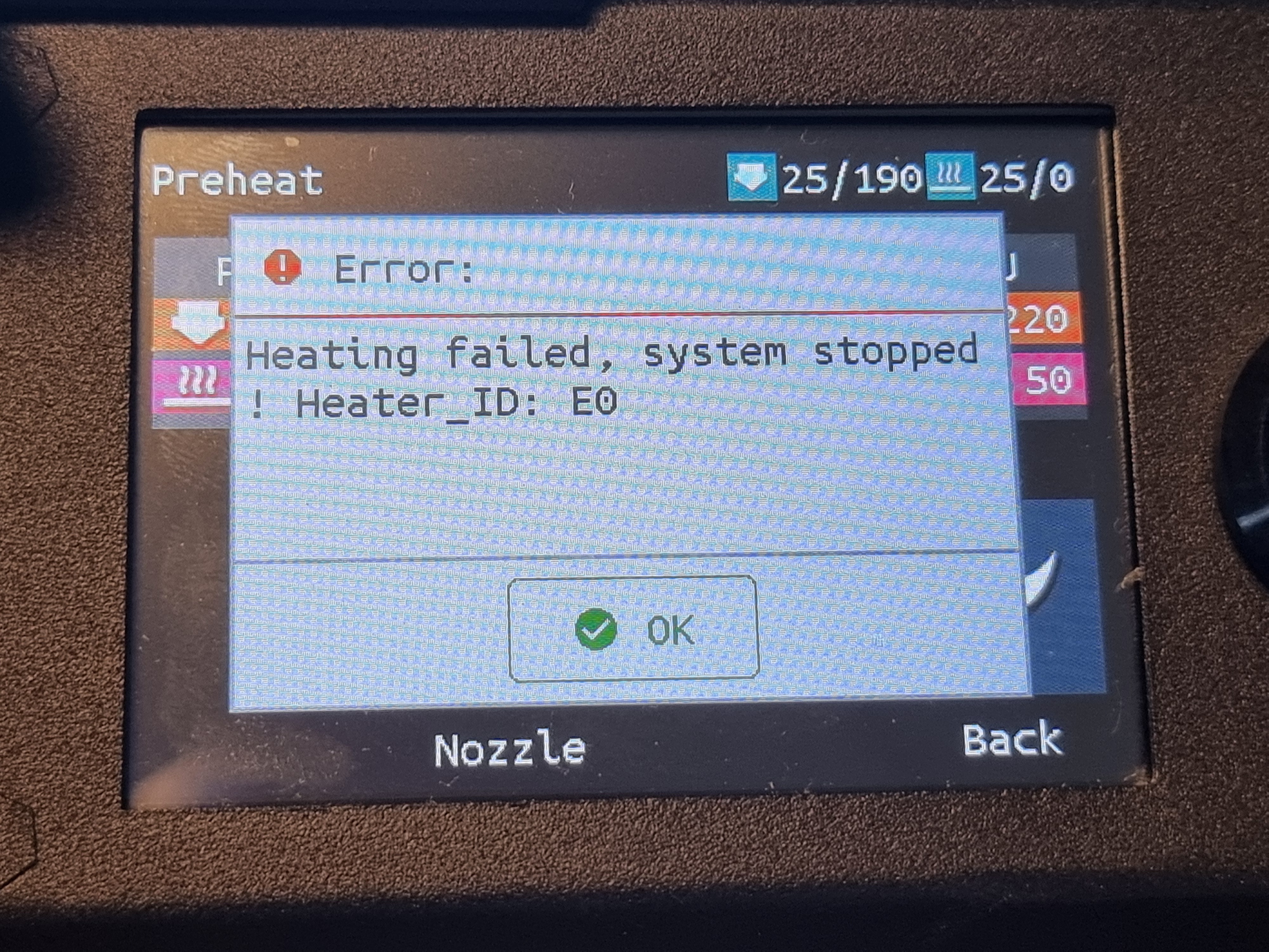
Yeah. Fixed it
UncleStewart
Haha SO true!
Probably why they "see" things clearer
That just works more like an antenna than anything else..
Looking closer on the X, Y, Z and E ports i observe that the ports are labeled different on the two cards.
Old SKR v1.4: Square pin = 1B, next pin = 1A, next = 2A, and last is 2B. Also the order is EN | STOP | DIR
New SKR MINI: Square pin = 2B, next pin = 1B, next = 1A, and last is 2A. The order looks like EN | STOP | DIR
Should i rearrange the wires in the JST so that the wire that on the old card was connected to 1B, also is connected to 1B on the new card, and so on?
The EN | STOP | DIR part is in the same direction in the pinouts, even the whole connector is upside-down on the SKR MINI. Why is this? Is this just labeling the round pins?
Arrghh, I have so many noob questions..
Haha, slowly it goes.. Changing the SKR v1.4 to a SKR MINI V3 isn't straight forward on the Biqu B1.
Here comes the fun part.
The Biqu B1 has all it's wires to the hotend via a USB-C cable. All wires from the motherboard goes to a card in the back of the printer, and fom there is a USB-C to a card in the hotend. This card splits up to TH0, CNCFAN, CNCAN1, FAN2 and HE0. Even power to the nozzle heater goes in the USB-C.
On the old SKR v1.4, the wire labeled DCIN were connected to FAN1 (GND - 12/24v), and FAN0 were connected to FAN0 (2.3 - 12/24v).
On the new SKR MINI V3 the DCIN wire is connected to FAN1 (12/24v - PC7), and FAN0 wire to FAN0 (12/24v - PC6).
The wire DCIN is not from PSU, but gives power to the card in the hotend.
In the printer.cfg all of fan-stuff are commented out, and the only thing is:
[fan_generic hotend_fan] #use for testing of hotend fan pin: PC7
pin: PC7
[fan] #part fan pin: PC6
Pin: PC6
This gives me sliders in Klipper for PC6 and PC7, and I can set FAN1 to 100%.
This should in (my) theory give power to the card in the hotend. But when i slide FAN0 in Klipper nothing happens with the fans.
When i disconnect the wires to the nozzle heater from the motherboard i now have about 24 volts on those wires, and this happens without heating the heater.
The reason for me starting this project was that one day i just got error message when heating the nozzle. First i bought a new heater, thermistor and the block they are mounted in. This did not help. So, now the motherboard is replaced and I've added a Raspberry PI with Klipper to the setup, and still no joy.
Thank you! This helped a lot.
Now, in the pinout for my old SKR v1.4 FAN0 is "12/24v" and "2.3"
, while FAN1 is "GND" and "12/24v"
.
What are the difference between FAN0 and FAN1 port on the motherboard?
(I've had a working 3D printer for 6 days, and have no experience with anything 3D printing related, so therefore these noob questions. )
Thanks. I've already used this one.
In the config file, some pins are named like "PB0", but other have a "!" in front, like "!PB1", and other a "^", like "^PC2". What are the "!" and "^" for?
What's the difference between a "PB0" and a "PC11".
Suspected that the SKR v1.4 original motherboard died (Hotend not heating), so advanced to the SKR MINI v3 + a Raspberry PI for Klipper.
I'm looking for "printer.cfg" that matches this setup..
Once upon a time I booted my laptop after I forgot it in the car over night. The classical spinning disk didn't make it. Lost everything on the disk. Best is to acclimatize the computer to room temperature if you have a spinning disk. Haven't tried with a SSD. I'm theory it should work (I believe). Sorry for no clear answer..