16
submitted 4 months ago by [email protected] to c/[email protected]

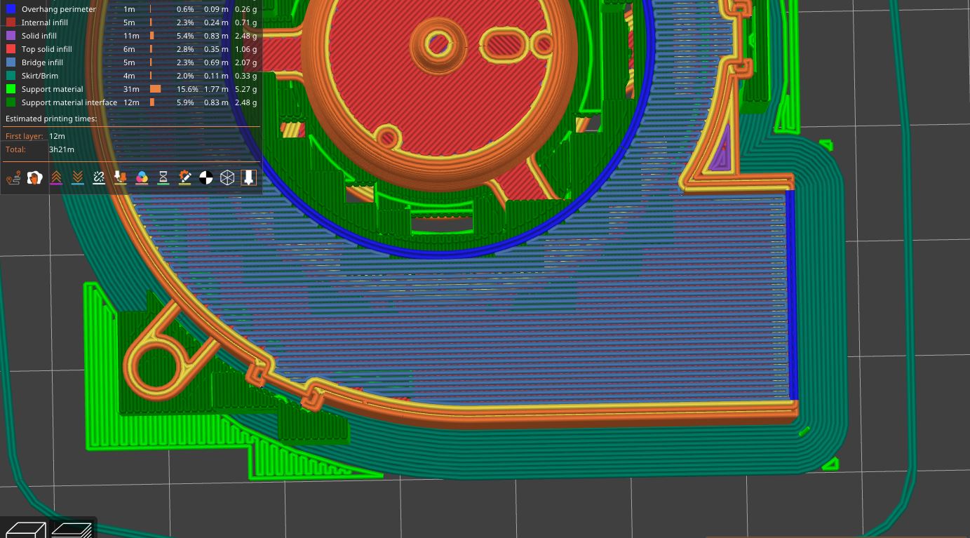
With this particular model, Prusaslicer is very optimistic about bridging and support generation:

  1. the right side (dark blue) has no support that could help with load-bearing
  2. the entire layer will be connected to those two lines
  3. more than 5cm long bridges

I don't think this gcode will successfully print.

How do fix adjust the cura setting to generate a printable output?

The model in question is: https://www.delta-fan.com/Download/3D/BUB0612HJ-00.stp

top 8 comments
sorted by: hot top controversial new old
[-] [email protected] 9 points 4 months ago
[-] [email protected] 3 points 4 months ago

Thanks. Is there also the option to rotate the pattern direction by 90° so it takes the short distances for bridges?

[-] [email protected] 4 points 4 months ago

"fill angle" under infill settings.

[-] [email protected] 2 points 4 months ago* (last edited 4 months ago)

Fill angle didn't change this as Prusaslicer sees this as a bridge.

Bridges will be printed using the best direction PrusaSlicer can detect, so this setting does not affect them.

https://help.prusa3d.com/article/infill_42#fill-angle

edit: just saw that there is a bridge angle setting that sets a fixed angle for every bridge.

[-] [email protected] 1 points 4 months ago

What filament do you want to use? Well tuned PLA might be able to bridge that far, no chance with PETG. What is your maximum acceptable sag?

It seems like the bridge lines do not attach to anything at the very end on the layer below. In Orca Slicer you need to enable "Ensure vertical thickness" to enforce that. I'd also rotate the bridge direction by 90°, this cuts down the length of the longest bridges by half. Bridge line spacing looks good to me. Make sure that the layer on top of the bridge is printed slowly and does not start in the middle, otherwise it will be pushed back and forth.

If it is just a mock-up, consider partially filling the interior or enabling "make overhangs printable". Both will alter geometry, but so will excessive sagging.

[-] [email protected] 1 points 4 months ago

Why are you printing this? Surface finish is super important to airflow in a design like this. Printing an overhang layer is not functionally adequate.

[-] [email protected] 3 points 4 months ago* (last edited 4 months ago)

Mockup. Will be a few weeks before the real fan is delivered.

[-] [email protected] 2 points 4 months ago

I would put the model in CAD and make it solid using a couple of booleans. FreeCAD can convert a mesh to a solid in the Part workbench.

this post was submitted on 14 Mar 2024
16 points (90.0% liked)

3DPrinting

14841 readers
38 users here now

3DPrinting is a place where makers of all skill levels and walks of life can learn about and discuss 3D printing and development of 3D printed parts and devices.

The r/functionalprint community is now located at: [email protected] or [email protected]

There are CAD communities available at: [email protected] or [email protected]

Rules

If you need an easy way to host pictures, https://catbox.moe may be an option. Be ethical about what you post and donate if you are able or use this a lot. It is just an individual hosting content, not a company. The image embedding syntax for Lemmy is ![](URL)

Moderation policy: Light, mostly invisible

founded 1 year ago
MODERATORS