this post was submitted on 06 Sep 2023
7 points (100.0% liked)

ErgoMechKeyboards

5877 readers
13 users here now

Ergonomic, split and other weird keyboards

Rules

Keep it ergo

Posts must be of/about keyboards that have a clear delineation between the left and right halves of the keyboard, column stagger, or both. This includes one-handed (one half doesn't exist, what clearer delineation is that!?)

i.e. no regular non-split¹ row-stagger and no non-split¹ ortholinear²

¹ split meaning a separation of the halves, whether fixed in place or entirely separate, both are fine.
² ortholinear meaning keys layed out in a grid

No Spam

No excessive posting/"shilling" for commercial purposes. Vendors are permitted to promote their products/services but keep it to a minimum and use the [vendor] flair. Posts that appear to be marketing without being transparent about it will be removed.

No Buy/Sell/Trade

This subreddit is not a marketplace, please post on r/mechmarket or other relevant marketplace.

Some useful links

founded 1 year ago
MODERATORS
 

Hi to all of you, Last year I decided to build a Skeletyl keyboard. For many reasons I decided to build it cheap instead of the kit. Despite my lack of experience in building anything it was not really a wise decision. Surprise... Anyway, I printed the the kit and wired the switches and bought the wrong microcontroller, put it of for half a year and then bought nicenanos. And now again I am out of my width. First I am searching for a holder for the nicenanos and second I am searching for some guidance for the pins I am supposed to use. I can read schematics and wild paint drawings, but the general advice for zmk with miryoku seems to be look at kicad files of similar keyboards. Those break me into pieces. Has anyone seen an holder for nicenanos and or some advice for the pins?

top 11 comments
sorted by: hot top controversial new old
[–] [email protected] 4 points 1 year ago

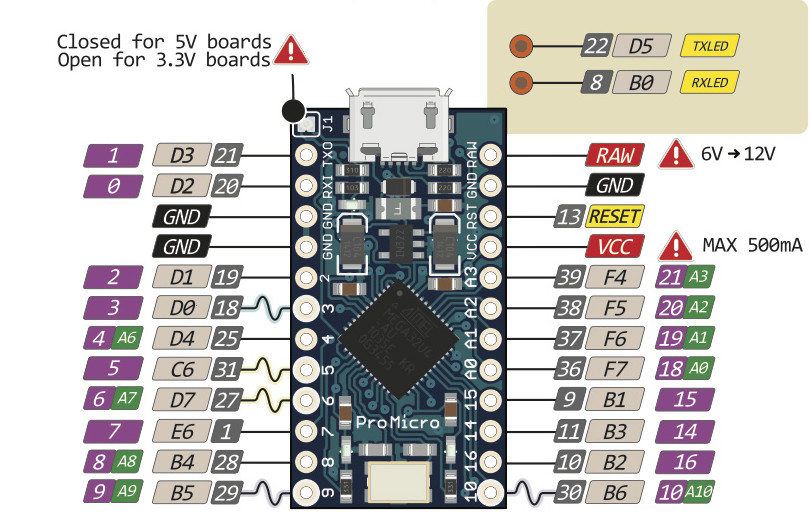
You can use any pins from D0 to D21. You can find out where each pin is by searching for "nicenano pinout". You will have to change the firmware later to fit the chosen pins.

If you already have a Firmware you can find the pins (at least in QMK) in the info.json or config.h file. I have never used ZMK but the used pins have to be in one of the files.

[–] [email protected] 2 points 1 year ago (2 children)

I made mine this year, but used pro micros instead of the nice nanos. Used a perf board to attach the controller and TRS connector. Zip ties to attach the perfboard to the case.

[–] [email protected] 1 points 1 year ago

I designed a holder for the nice!nano and the battery. Now I only need to find a i/o switch which fits to the TRS hole. Wire everything up and try to get the ZMK right.

[–] [email protected] 1 points 1 year ago

That's an nice idea. My dream would be something like this , but for the nicenano. It also should hold a battery. However, haven't designed anything yet.

[–] [email protected] 2 points 1 year ago (1 children)

haven't handwired a board yet, but no matter whether it's with pcb or handwired, you'll either need enough pins to direct-connect every single switch (probably not the case) or you'll have to use a diode-matrix. for learning about those, i'd suggest taking a look at this kbd.news article: https://kbd.news/The-Japanese-duplex-matrix-1391.html

for a general handwiring guide, check out Joe Scotto's stuff, e.g. https://www.youtube.com/watch?v=hjml-K-pV4E

[–] [email protected] 2 points 1 year ago (1 children)

I have already wired the switches. Guided by Scotto's videos. It's a 5x4 matrix with no keys on the bottom row on 1,2,9,10. There are similar shields for the zmk firmware. My problem lies in the identification of row/column to pin connection.

[–] [email protected] 3 points 1 year ago* (last edited 1 year ago)

Columns starting from the pinky: F5, B6, D7, E6, B4

Rows starting from the top: F7, C6, D4, B5

The pinout for the pro micro and nice!nano should be the same, I'm just using the AVR pin names but F7 is the same as pin 18, for instance.

Edit: Looks like you wired COL2ROW instead or ROW2COL. By the way, the wiring of the columns is a bit different from the original.

But none of this really matters, your keyboard looks great! You should be able to connect to any digital pins and program it to work just fine.

[–] [email protected] 2 points 1 year ago (1 children)

Hey, in the bastardkb docs, there is a tray holder for the nano/pro micro that looks to fit inside your build, also works on my Scylla. It's its own repo. I think you can slip the battery between the pins.

Then check if your are rol2col or col2row, there is explainer inside the zmk docs.

Next, find the pins, n!n pinout, and make sure your overlay and dtsii? File has the right order of matrix,. eg the 0,0 0,1... 0,5 and that it matches with how you wired your board. And the right row2col setting.

Zmk docs also has a nice explainer for he matrix stuff.

[–] [email protected] 2 points 1 year ago (1 children)

You mean this one? I found that, but it was part of the kit I didn't want to use. Also I missed the opportunity when somebody sold some on them on the discord channel. By now I designed a 3d printed tray, which holds 401430 LiPos (they do not fit below the nice!nano, but I cannot find 301230 for sale). Next step will be the wiring and before that I will have to figure out the pinout part.

[–] [email protected] 2 points 1 year ago (1 children)

https://github.com/Bastardkb/Skeletyl/blob/main/things/pro%20micro%20mount%20plate/pro%20micro%20mount%20plate%20v2.stl

Is the one that is working for me. I assume the other kb from Bastard would fit, but only a guess.

I am wiring mine currently and did a bit of debugging, but I'm a trial and error guy and nearly done. So I would say just jump in :)

[–] [email protected] 3 points 1 year ago

Oh, I missed that one. Thanks. However, I designed my own one. Since my design has a pocket for the battery I think I will stick to it.